Overview of earthing methods and their characteristics
|
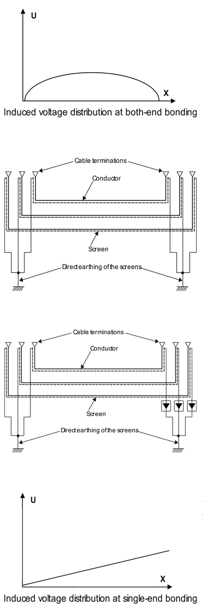
Both-ends bonding
A system is both ends bonded if the arrangements are such that the cable sheaths provide path for circulating currents at normal conditions. This will cause losses in the screen, which reduce the cable current carrying capacity.
These losses are smaller for cables in trefoil formation than in flat formation with separation
Single-point bonding
A system is single point bonded if the arrangements are such that the cable sheaths provide no path for the flow of circulating currents or external fault currents.
In such case, a voltage will be induced between screen of adjacent phases of the cable circuit and between screen and earth, but no current will flow.
This induced voltage is proportional to cable length and current. Single-point bonding can only be used for limited route lengths, but in general the accepted screen voltage potential limits the length.
Cross-bonding
A system is cross-bonded if the arrangements are such that the circuit provides electrically continuous sheath runs from earthed termination to earthed termination but with the sheaths so sectionalized and cross-connected in order to eliminate the sheath circulating currents.
In such case, a voltage will be induced between screen and earth, but no significant current will flow.
The maximum induced voltage will appear at the link boxes for cross-bonding.
This method permits a cable current-carrying capacity as high as with single-point bonding but longer route lengths than the latter.
It requires screen separation and additional link boxes.
|
 |


 Technical Information